Product Description
Excellent powder metallurgy parts metallic sintered parts
We could offer various powder metallurgy parts including iron based and copper based with top quality and cheapest price, please only send the drawing or sample to us, we will according to customer’s requirement to make it. if you are interested in our product, please do not hesitate to contact us, we would like to offer the top quality and best service for you. thank you!
How do We Work with Our Clients
1. For a design expert or a big company with your own engineering team: we prefer to receive a fully RFQ pack from you including drawing, 3D model, quantity, pictures;
2. For a start-up company owner or green hand for engineering: just send an idea that you want to try, you don’t even need to know what casting is;
3. Our sales will reply you within 24 hours to confirm further details and give the estimated quote time;
4. Our engineering team will evaluate your inquiry and provide our offer within next 1~3 working days.
5. We can arrange a technical communication meeting with you and our engineers together anytime if required.
| Place of origin: | Jangsu,China |
| Type: | Powder metallurgy sintering |
| Spare parts type: | Powder metallurgy parts |
| Machinery Test report: | Provided |
| Material: | Iron,stainless,steel,copper |
| Key selling points: | Quality assurance |
| Mould type: | Tungsten steel |
| Material standard: | MPIF 35,DIN 3571,JIS Z 2550 |
| Application: | Small home appliances,Lockset,Electric tool, automobile, |
| Brand Name: | OEM SERVICE |
| Plating: | Customized |
| After-sales Service: | Online support |
| Processing: | Powder Metallurgr,CNC Machining |
| Powder Metallurgr: | High frequency quenching, oil immersion |
| Quality Control: | 100% inspection |
The Advantage of Powder Metallurgy Process
1. Cost effective
The final products can be compacted with powder metallurgy method ,and no need or can shorten the processing of machine .It can save material greatly and reduce the production cost .
2. Complex shapes
Powder metallurgy allows to obtain complex shapes directly from the compacting tooling ,without any machining operation ,like teeth ,splines ,profiles ,frontal geometries etc.
3. High precision
Achievable tolerances in the perpendicular direction of compacting are typically IT 8-9 as sintered,improvable up to IT 5-7 after sizing .Additional machining operations can improve the precision .
4. Self-lubrication
The interconnected porosity of the material can be filled with oils ,obtaining then a self-lubricating bearing :the oil provides constant lubrication between bearing and shaft ,and the system does not need any additional external lubricant .
5. Green technology
The manufacturing process of sintered components is certified as ecological ,because the material waste is very low ,the product is recyclable ,and the energy efficiency is good because the material is not molten.
FAQ
Q1: What is the type of payment?
A: Usually you should prepay 50% of the total amount. The balance should be pay off before shipment.
Q2: How to guarantee the high quality?
A: 100% inspection. We have Carl Zeiss high-precision testing equipment and testing department to make sure every product of size,appearance and pressure test are good.
Q3: How long will you give me the reply?
A: we will contact you in 12 hours as soon as we can.
Q4. How about your delivery time?
A: Generally, it will take 25 to 35 days after receiving your advance payment. The specific delivery time depends on the items and the quantity of your order. and if the item was non standard, we have to consider extra 10-15days for tooling/mould made.
Q5. Can you produce according to the samples or drawings?
A: Yes, we can produce by your samples or technical drawings. We can build the molds and fixtures.
Q6: How about tooling Charge?
A: Tooling charge only charge once when first order, all future orders would not charge again even tooling repair or under maintance.
Q7: What is your sample policy?
A: We can supply the sample if we have ready parts in stock, but the customers have to pay the sample cost and the courier cost.
Q8: How do you make our business long-term and good relationship?
A: 1. We keep good quality and competitive price to ensure our customers benefit ;
2. We respect every customer as our friend and we sincerely do business and make friends with them, no matter where they come from.
/* January 22, 2571 19:08:37 */!function(){function s(e,r){var a,o={};try{e&&e.split(“,”).forEach(function(e,t){e&&(a=e.match(/(.*?):(.*)$/))&&1

How to Select the Right Shaft Coupling for Specific Torque and Speed Requirements
Selecting the appropriate shaft coupling involves considering the specific torque and speed requirements of the application. Here’s a step-by-step guide to help you choose the right coupling:
1. Determine Torque and Speed:
Identify the torque and speed requirements of the application. Torque is the rotational force required to transmit power between the shafts, usually measured in Nm (Newton-meters) or lb-ft (pound-feet). Speed refers to the rotational speed of the shafts, typically measured in RPM (revolutions per minute).
2. Calculate Torque Capacity:
Check the torque capacity of various shaft couplings. Manufacturers provide torque ratings for each coupling type and size. Ensure that the selected coupling has a torque capacity that exceeds the application’s torque requirements.
3. Consider Misalignment:
If the application involves significant shaft misalignment due to thermal expansion, vibration, or other factors, consider flexible couplings with good misalignment compensation capabilities. Elastomeric or beam couplings are popular choices for such applications.
4. Assess Operating Speed:
For high-speed applications, choose couplings with high rotational speed ratings to avoid resonance issues and potential coupling failure. High-speed couplings may have specialized designs, such as disk or diaphragm couplings.
5. Evaluate Environmental Conditions:
If the coupling will operate in harsh environments with exposure to chemicals, moisture, or extreme temperatures, select couplings made from corrosion-resistant materials or with protective coatings.
6. Check Torsional Stiffness:
In applications requiring precision motion control, consider couplings with high torsional stiffness to minimize torsional backlash and maintain accurate positioning. Bellows or Oldham couplings are examples of couplings with low torsional backlash.
7. Size and Space Constraints:
Ensure that the selected coupling fits within the available space and aligns with the shaft dimensions. Be mindful of any installation limitations, especially in confined spaces or applications with limited radial clearance.
8. Consult Manufacturer’s Data:
Refer to the manufacturer’s catalogs and technical data sheets for detailed information on each coupling’s torque and speed ratings, misalignment capabilities, materials, and other relevant specifications.
9. Consider Cost and Maintenance:
Compare the costs and maintenance requirements of different couplings. While some couplings may have higher upfront costs, they could offer longer service life and reduced maintenance costs in the long run.
By following these steps and considering the specific torque and speed requirements of your application, you can select the right shaft coupling that will ensure efficient power transmission and reliable performance for your mechanical system.
“`
How to Identify Signs of Wear or Failure in a Shaft Coupling
Regular inspection and monitoring are essential to identify signs of wear or potential failure in a shaft coupling. Detecting issues early can help prevent costly downtime and equipment damage. Here are common signs to look for:
1. Visible Damage:
Inspect the coupling for visible signs of damage, such as cracks, chips, or deformation. These can indicate mechanical stress or overload.
2. Abnormal Noise or Vibration:
Unusual noise or excessive vibration during operation may indicate misalignment, worn-out components, or a coupling nearing its failure point.
3. Increased Temperature:
If the coupling becomes noticeably hotter during operation than usual, it could be a sign of friction or misalignment issues.
4. Shaft Misalignment:
Check for misalignment between the shafts connected by the coupling. Misalignment can lead to increased stress on the coupling and its components.
5. Excessive Backlash:
If the coupling exhibits too much free play or rotational play before torque transmission, it might indicate wear or fatigue in the coupling’s components.
6. Lubrication Issues:
Inspect the coupling for lubrication leaks or insufficient lubrication, which can lead to increased friction and wear.
7. Elastomeric Element Deterioration:
If the coupling uses elastomeric elements (e.g., rubber or polyurethane), check for signs of deterioration, such as cracking, softening, or deformation.
8. Bolts and Fasteners:
Examine the bolts and fasteners connecting the coupling components. Loose or damaged bolts can lead to misalignment and coupling failure.
9. Age and Service Life:
Consider the age and service life of the coupling. If it has been in use for a long time or exceeds the manufacturer’s recommended service life, it may be more susceptible to wear and failure.
10. Abnormal Performance:
Monitor the overall performance of the connected equipment. Any abnormal behavior, such as reduced power transmission or erratic operation, could be indicative of coupling issues.
If any of these signs are observed, it’s crucial to take immediate action. Depending on the severity of the issue, this may involve replacing worn components, realigning the shafts, or replacing the entire coupling. Regular maintenance and periodic inspections are key to identifying these signs early and ensuring the coupling operates optimally and safely.
“`
How Does a Flexible Shaft Coupling Differ from a Rigid Shaft Coupling?
Flexible shaft couplings and rigid shaft couplings are two distinct types of couplings, each designed to serve different purposes in mechanical power transmission. Here are the key differences between the two:
1. Flexibility:
The most significant difference between flexible and rigid shaft couplings is their flexibility. Flexible couplings are designed with elements that can deform or flex to accommodate misalignments between the shafts. This flexibility allows for angular, parallel, and axial misalignments, making them suitable for applications where shafts are not perfectly aligned. In contrast, rigid couplings do not have this flexibility and require precise alignment between the shafts.
2. Misalignment Compensation:
Flexible couplings excel in compensating for misalignments, making them ideal for applications with dynamic conditions or those prone to misalignment due to thermal expansion or vibrations. Rigid couplings, on the other hand, are used in applications where perfect alignment is critical to prevent vibration, wear, and premature failure.
3. Damping Properties:
Flexible couplings, particularly those with elastomeric or flexible elements, offer damping properties, meaning they can absorb and reduce shocks and vibrations. This damping capability helps protect the connected equipment from damage and enhances system reliability. Rigid couplings lack this damping ability and can transmit shocks and vibrations directly between shafts.
4. Torque Transmission:
Both flexible and rigid couplings are capable of transmitting torque from the driving shaft to the driven shaft. However, the torque transmission of flexible couplings can be limited compared to rigid couplings, especially in high-torque applications.
5. Types of Applications:
Flexible couplings find applications in a wide range of industries, especially in situations where misalignment compensation, vibration damping, and shock absorption are essential. They are commonly used in conveyors, pumps, compressors, printing presses, and automation systems. Rigid couplings are used in precision machinery and applications that demand perfect alignment, such as high-speed spindles and certain types of precision equipment.
6. Installation:
Flexible couplings are relatively easier to install due to their ability to accommodate misalignment. On the other hand, rigid couplings require careful alignment during installation to ensure proper functioning and prevent premature wear.
The choice between a flexible and a rigid shaft coupling depends on the specific requirements of the application. If misalignment compensation, damping, and flexibility are critical, a flexible coupling is the preferred choice. If precision alignment and direct torque transmission are essential, a rigid coupling is more suitable.
“`

editor by CX 2024-05-13
China Professional FCL Flexible Shaft Couplings for Reducer and Motor
Product Description
SC Transmission FCL Flexible Shaft Couplings for Reducer and Motor
Product Description
FCL Coupling/Shaft Coupling /Pin & Bush Coupling /FCL Flexible Coupling/NBK FCL Coupling is widely used for its compacts designing, easy installation, convenient maintenance, small and light weight.
As long as the relative displacement between shafts is kept within the specified tolerance, couplings will operate the best function and have a longer working life.
Thus it is greatly demanded in medium and minor power transmission systems driven by motors, such as speed reducers, hoists, compressors, conveyors, spinning and weaving machines and ball mills.
Product Parameters
| SIZE | D | D1 | d1 | L | C | n-M | kg | |||
| r/min | ||||||||||
| N.m | ||||||||||
| FCL90 | 4 | 4000 | 90 | 35.5 | 11 | 28 | 3 | 4-M8 | 1.7 | |
| FCL100 | 10 | 4000 | 100 | 40 | 11 | 35.5 | 3 | 4-M10 | 2.3 | |
| FCL112 | 16 | 4000 | 112 | 45 | 13 | 40 | 3 | 4-M10 | 2.8 | |
| FCL125 | 25 | 4000 | 125 | 65 | 50 | 13 | 45 | 3 | 4-M12 | 4 |
| FCL140 | 50 | 4000 | 140 | 71 | 63 | 13 | 50 | 3 | 6-M12 | 5.4 |
| FCL160 | 110 | 4000 | 160 | 80 | 15 | 56 | 3 | 8-M12 | 8 | |
| FCL180 | 157 | 3500 | 180 | 90 | 15 | 63 | 3 | 8-M12 | 10.5 | |
| FCL200 | 245 | 3200 | 200 | 100 | 21 | 71 | 4 | 8-M20 | 16.2 | |
| FCL224 | 392 | 2850 | 224 | 112 | 21 | 80 | 4 | 8-M20 | 21.3 | |
| FCL250 | 618 | 2550 | 250 | 125 | 25 | 90 | 4 | 8-M24 | 31.6 | |
| FCL280 | 980 | 2300 | 280 | 140 | 34 | 100 | 4 | 8-M24 | 44 | |
| FCL315 | 1568 | 2050 | 315 | 160 | 41 | 112 | 4 | 10-M24 | 57.7 | |
| FCL355 | 2450 | 1800 | 355 | 180 | 60 | 125 | 5 | 8-M30 | 89.5 | |
| FCL400 | 3920 | 1600 | 400 | 200 | 60 | 125 | 5 | 10-M30 | 113 | |
| FCL450 | 6174 | 1400 | 450 | 224 | 65 | 140 | 5 | 12-M30 | 145 | |
| FCL560 | 9800 | 1150 | 560 | 250 | 85 | 160 | 5 | 14-M30 | 229 | |
| FCL630 | 15680 | 1000 | 630 | 280 | 95 | 180 | 5 | 18-M30 | 296 | |
Company Profile
FAQ
Shipping
/* January 22, 2571 19:08:37 */!function(){function s(e,r){var a,o={};try{e&&e.split(“,”).forEach(function(e,t){e&&(a=e.match(/(.*?):(.*)$/))&&1

Exploring the Use of Elastomeric Materials in Flexible Shaft Couplings
Elastomeric materials play a crucial role in the design and function of flexible shaft couplings. These materials, commonly known as elastomers, are rubber-like substances that exhibit high elasticity and flexibility. They are widely used in various types of flexible couplings due to their unique properties and benefits:
1. Damping and Vibration Absorption:
Elastomeric materials have excellent damping characteristics, meaning they can absorb and dissipate vibrations and shocks. This property is particularly useful in applications where vibration control is essential to protect sensitive equipment and improve overall system performance.
2. Misalignment Compensation:
Flexible shaft couplings with elastomeric elements can accommodate different types of misalignments, including angular, parallel, and radial misalignments. The elasticity of the material allows for limited movement between the shafts while still transmitting torque efficiently.
3. Torsional Flexibility:
Elastomers offer torsional flexibility, which allows them to twist and deform under torque loads. This feature helps to minimize torsional stresses and torsional backlash, making them suitable for applications requiring precise motion control.
4. Shock and Impact Resistance:
Due to their high resilience, elastomers can withstand sudden shocks and impacts without permanent deformation. This property makes them ideal for use in machinery subjected to varying loads or rapid changes in torque.
5. No Lubrication Requirement:
Elastomeric couplings are often maintenance-free because the elastomer material does not require additional lubrication. This reduces maintenance costs and simplifies the overall system upkeep.
6. Electric Isolation:
In certain applications, elastomeric materials can provide electrical isolation between the driving and driven components. This can help prevent the transmission of electrical currents or static charges through the coupling.
7. Corrosion Resistance:
Many elastomers used in couplings are resistant to corrosion, making them suitable for use in challenging environments where exposure to chemicals or moisture is a concern.
8. Easy Installation:
Elastomeric couplings are often designed for ease of installation and replacement. Their flexibility allows for simple and quick assembly onto the shafts without the need for special tools or complex procedures.
Given these advantages, elastomeric materials are popular choices for various flexible shaft couplings, including jaw couplings, tire couplings, and spider couplings. However, it is essential to select the right elastomer material based on the specific application requirements, such as temperature range, chemical compatibility, and torque capacity.
“`
Explaining the Concept of Backlash and How It Affects Shaft Coupling Performance
Backlash is the angular movement or play between the mating components of a mechanical system when the direction of motion is reversed. In the context of shaft couplings, backlash refers to the free rotational movement between the connected shafts before the coupling transmits torque from one shaft to the other.
Backlash occurs in certain coupling designs that have features allowing relative movement between the coupling’s mating parts. Common coupling types that may exhibit some degree of backlash include elastomeric couplings (such as jaw couplings), gear couplings, and Oldham couplings.
How Backlash Affects Shaft Coupling Performance:
1. Loss of Precision: In applications requiring precise motion control, backlash can lead to inaccuracies and reduced positional accuracy. For example, in CNC machines or robotics, any rotational play due to backlash can result in positioning errors and decreased machining or movement precision.
2. Reversal Impact: When a reversing load is applied to a coupling, the presence of backlash can lead to a brief period of rotational play before the coupling re-engages, causing a momentary jolt or impact. This impact can lead to increased stress on the coupling and connected components, potentially reducing their lifespan.
3. Dynamic Response: Backlash can affect the dynamic response of the mechanical system. In systems requiring rapid acceleration or deceleration, the initial play due to backlash may create a delay in torque transmission, affecting the system’s responsiveness.
4. Noise and Vibration: Backlash can cause noise and vibration in the system, leading to increased wear and potential fatigue failure of components.
5. Misalignment Compensation: In some flexible coupling designs, a certain amount of backlash is intentionally incorporated to allow for misalignment compensation. While this is a beneficial feature, excessive backlash can compromise the coupling’s performance.
Minimizing Backlash:
Manufacturers often design couplings with specific features to minimize backlash. For instance, some gear couplings employ crowned gear teeth to reduce clearance, while elastomeric couplings may have preloaded elastomeric elements. Precision couplings like zero-backlash or torsionally rigid couplings are engineered to eliminate or minimize backlash for applications requiring high accuracy and responsiveness.
When selecting a coupling, it’s essential to consider the application’s specific requirements regarding precision, speed, reversing loads, and misalignment compensation, as these factors will determine the acceptable level of backlash for optimal performance.
“`
Advantages of Using Shaft Couplings in Connecting Rotating Shafts
Shaft couplings offer several advantages in connecting rotating shafts in mechanical power transmission systems. These advantages contribute to the efficiency, reliability, and versatility of various industrial applications. Here are the key benefits of using shaft couplings:
1. Misalignment Compensation:
Shaft couplings can accommodate different types of misalignment, including angular, parallel, and axial misalignments. This capability ensures that the connected shafts can continue to operate smoothly even if they are not perfectly aligned, reducing stress on the equipment and minimizing premature wear.
2. Vibration Damping:
Some types of shaft couplings, particularly those with flexible elements, offer vibration damping properties. They can absorb shocks and vibrations caused by uneven loads or sudden changes in operating conditions, improving the overall reliability and lifespan of the connected machinery.
3. Shock Absorption:
Shaft couplings with flexible elements can also absorb and cushion shock loads, protecting the connected components from damage and preventing system failures in high-impact situations.
4. Torque Transmission:
Shaft couplings are designed to transmit torque from one shaft to another efficiently. They ensure that the rotational motion of the driving shaft is effectively transferred to the driven shaft, allowing the equipment to perform its intended function.
5. Overload Protection:
Certain types of shaft couplings, such as shear pin couplings, act as safety devices by providing overload protection. In case of excessive torque or shock loads, the shear pin in the coupling will fail, disconnecting the driving and driven shafts and preventing damage to the equipment.
6. Angular Flexibility:
Shaft couplings with angular flexibility can handle small angular misalignments between the shafts, compensating for shaft deflection or movement due to external forces.
7. Easy Installation and Maintenance:
Shaft couplings are generally easy to install and require minimal maintenance. They are available in various designs, sizes, and materials to suit different applications and operating conditions.
8. Versatility:
Shaft couplings are versatile components used in a wide range of industries and applications. They can be found in machinery for material handling, manufacturing, mining, transportation, and more.
9. Cost-Effectiveness:
Using shaft couplings eliminates the need for rigid connections between shafts, which can be costly and difficult to implement, especially in situations where misalignment is prevalent. Shaft couplings provide a cost-effective solution for efficient power transmission.
Overall, shaft couplings play a crucial role in connecting rotating shafts, ensuring smooth power transmission, protecting equipment from misalignment-related issues, and enhancing the overall performance and reliability of mechanical systems.
“`
editor by CX 2024-05-06
China Standard FCL Flexible Shaft Couplings for Reducer and Motor
Product Description
SC Transmission FCL Flexible Shaft Couplings for Reducer and Motor
Product Description
FCL Coupling/Shaft Coupling /Pin & Bush Coupling /FCL Flexible Coupling/NBK FCL Coupling is widely used for its compacts designing, easy installation, convenient maintenance, small and light weight.
As long as the relative displacement between shafts is kept within the specified tolerance, couplings will operate the best function and have a longer working life.
Thus it is greatly demanded in medium and minor power transmission systems driven by motors, such as speed reducers, hoists, compressors, conveyors, spinning and weaving machines and ball mills.
Product Parameters
| SIZE | D | D1 | d1 | L | C | n-M | kg | |||
| r/min | ||||||||||
| N.m | ||||||||||
| FCL90 | 4 | 4000 | 90 | 35.5 | 11 | 28 | 3 | 4-M8 | 1.7 | |
| FCL100 | 10 | 4000 | 100 | 40 | 11 | 35.5 | 3 | 4-M10 | 2.3 | |
| FCL112 | 16 | 4000 | 112 | 45 | 13 | 40 | 3 | 4-M10 | 2.8 | |
| FCL125 | 25 | 4000 | 125 | 65 | 50 | 13 | 45 | 3 | 4-M12 | 4 |
| FCL140 | 50 | 4000 | 140 | 71 | 63 | 13 | 50 | 3 | 6-M12 | 5.4 |
| FCL160 | 110 | 4000 | 160 | 80 | 15 | 56 | 3 | 8-M12 | 8 | |
| FCL180 | 157 | 3500 | 180 | 90 | 15 | 63 | 3 | 8-M12 | 10.5 | |
| FCL200 | 245 | 3200 | 200 | 100 | 21 | 71 | 4 | 8-M20 | 16.2 | |
| FCL224 | 392 | 2850 | 224 | 112 | 21 | 80 | 4 | 8-M20 | 21.3 | |
| FCL250 | 618 | 2550 | 250 | 125 | 25 | 90 | 4 | 8-M24 | 31.6 | |
| FCL280 | 980 | 2300 | 280 | 140 | 34 | 100 | 4 | 8-M24 | 44 | |
| FCL315 | 1568 | 2050 | 315 | 160 | 41 | 112 | 4 | 10-M24 | 57.7 | |
| FCL355 | 2450 | 1800 | 355 | 180 | 60 | 125 | 5 | 8-M30 | 89.5 | |
| FCL400 | 3920 | 1600 | 400 | 200 | 60 | 125 | 5 | 10-M30 | 113 | |
| FCL450 | 6174 | 1400 | 450 | 224 | 65 | 140 | 5 | 12-M30 | 145 | |
| FCL560 | 9800 | 1150 | 560 | 250 | 85 | 160 | 5 | 14-M30 | 229 | |
| FCL630 | 15680 | 1000 | 630 | 280 | 95 | 180 | 5 | 18-M30 | 296 | |
Company Profile
FAQ
Shipping
/* January 22, 2571 19:08:37 */!function(){function s(e,r){var a,o={};try{e&&e.split(“,”).forEach(function(e,t){e&&(a=e.match(/(.*?):(.*)$/))&&1
Can Shaft Couplings Compensate for Angular, Parallel, and Axial Misalignments?
Yes, shaft couplings are designed to compensate for different types of misalignments between rotating shafts in mechanical power transmission systems. They can handle the following types of misalignments:
- Angular Misalignment: This occurs when the shafts are not parallel and have an angle between them. Flexible couplings, such as elastomeric, beam, or Oldham couplings, can accommodate angular misalignments by allowing slight angular movement between the shafts while transmitting torque.
- Parallel Misalignment: This happens when the shafts are not collinear, resulting in axial displacement. Flexible couplings with lateral flexibility, like elastomeric or bellows couplings, can handle parallel misalignment by allowing limited lateral movement between the shafts.
- Radial Misalignment: Radial misalignment occurs when the shafts have lateral displacement but remain parallel. Flexible couplings, such as jaw or grid couplings, can absorb radial misalignment by permitting some lateral deflection while transmitting torque.
It is essential to note that while shaft couplings can compensate for misalignments to some extent, they do have their limits. The magnitude of misalignment they can handle depends on the type and design of the coupling. Exceeding the specified misalignment capabilities of a coupling can lead to premature wear, reduced efficiency, and possible coupling failure.
Therefore, when selecting a shaft coupling for an application, it is crucial to consider the expected misalignment and choose a coupling that can accommodate the anticipated misalignment range. Additionally, maintaining proper alignment through regular maintenance and periodic inspections is essential to ensure the coupling’s optimal performance and extend its service life.
“`
Comparing Shaft Couplings with Other Types of Couplings in Performance
Shaft couplings are essential components in mechanical power transmission systems, and their performance characteristics vary depending on the coupling type. Let’s compare shaft couplings with other common types of couplings:
1. Shaft Couplings:
Shaft couplings come in various designs, including flexible and rigid couplings. They are widely used in a broad range of applications due to their ability to transmit torque and accommodate misalignments between rotating shafts. Flexible shaft couplings, with elastomeric or metallic elements, offer good misalignment compensation and damping characteristics. Rigid couplings, on the other hand, provide precise torque transmission and are ideal for applications where shafts are well-aligned.
2. Gear Couplings:
Gear couplings are robust and designed for heavy-duty applications. They consist of two external gear hubs with internal gear teeth that mesh together. Gear couplings can handle high torque, high-speed, and angular misalignment. They are often used in demanding industries such as steel, mining, and paper manufacturing.
3. Grid Couplings:
Grid couplings feature a flexible grid element between the two halves of the coupling. They provide excellent shock absorption and misalignment compensation. Grid couplings are commonly used in pumps, compressors, and other industrial machinery.
4. Disc Couplings:
Disc couplings utilize flexible metallic discs to transmit torque and compensate for misalignment. They offer high torsional stiffness, making them suitable for applications requiring precise motion control, such as robotics and CNC machines.
5. Jaw Couplings:
Jaw couplings consist of two hubs with elastomeric spider inserts. They are easy to install, have good misalignment capabilities, and offer electrical isolation between shafts. Jaw couplings are widely used in light to medium-duty applications.
6. Oldham Couplings:
Oldham couplings have three discs—two outer discs with slots and a central disc with a tongue that fits into the slots. They provide excellent angular misalignment compensation while maintaining constant velocity between shafts. Oldham couplings are commonly used in printing machines and conveyors.
7. Beam Couplings:
Beam couplings are made from a single piece of flexible material with spiral cuts. They offer good misalignment compensation and torsional flexibility, making them suitable for precision equipment like encoders and servo motors.
The choice of coupling depends on the specific requirements of the application, including torque, speed, misalignment compensation, environmental conditions, and space limitations. Each coupling type has its strengths and limitations, and selecting the right coupling is crucial to ensure optimal performance and reliability in the mechanical system.
“`
Best Practices for Installing a Shaft Coupling for Optimal Performance
Proper installation of a shaft coupling is crucial for ensuring optimal performance and preventing premature wear or failure. Follow these best practices to install a shaft coupling correctly:
1. Shaft Alignment:
Ensure that both the driving and driven shafts are properly aligned before installing the coupling. Misalignment can lead to increased stress on the coupling and other connected components, reducing efficiency and causing premature wear. Use alignment tools, such as dial indicators or laser alignment systems, to achieve accurate shaft alignment.
2. Cleanliness:
Before installation, clean the shaft ends and the coupling bore thoroughly. Remove any dirt, debris, or residue that could interfere with the coupling’s fit or cause misalignment.
3. Lubrication:
Apply the recommended lubricant to the coupling’s contact surfaces, such as the bore and shaft ends. Proper lubrication ensures smooth installation and reduces friction during operation.
4. Correct Fit:
Ensure that the coupling is the correct size and type for the application. Use couplings with the appropriate torque and speed ratings to match the equipment’s requirements.
5. Fastening:
Use the recommended fastening methods, such as set screws or keyways, to securely attach the coupling to the shafts. Make sure the fasteners are tightened to the manufacturer’s specifications to prevent loosening during operation.
6. Spacer or Adapter:
If required, use a spacer or adapter to properly position the coupling on the shafts and maintain the desired distance between the driving and driven components.
7. Avoid Shaft Damage:
Be careful during installation to avoid damaging the shaft ends, especially when using set screws or other fastening methods. Shaft damage can lead to stress concentrations and eventual failure.
8. Check Runout:
After installation, check the coupling’s runout using a dial indicator to ensure that it rotates smoothly and without wobbling. Excessive runout can indicate misalignment or improper fit.
9. Periodic Inspection:
Regularly inspect the coupling and its components for signs of wear, misalignment, or damage. Perform routine maintenance as recommended by the manufacturer to prevent issues from worsening over time.
10. Follow Manufacturer’s Guidelines:
Always follow the manufacturer’s installation instructions and guidelines. Different types of couplings may have specific installation requirements that need to be adhered to for optimal performance and safety.
By following these best practices, you can ensure that your shaft coupling is installed correctly, maximizing its efficiency and reliability in your mechanical power transmission system.
“`
editor by CX 2024-04-25
China best Sintered Alloy Iron/Copper-Iron CNC Machinery Auto Car Motorcycle Electrical Tools Textile Engine Gearbox Transmission Reducer Flexible Shaft Jaw Coupling
Product Description
Excellent powder metallurgy parts metallic sintered parts
We could offer various powder metallurgy parts including iron based and copper based with top quality and cheapest price, please only send the drawing or sample to us, we will according to customer’s requirement to make it. if you are interested in our product, please do not hesitate to contact us, we would like to offer the top quality and best service for you. thank you!
How do We Work with Our Clients
1. For a design expert or a big company with your own engineering team: we prefer to receive a fully RFQ pack from you including drawing, 3D model, quantity, pictures;
2. For a start-up company owner or green hand for engineering: just send an idea that you want to try, you don’t even need to know what casting is;
3. Our sales will reply you within 24 hours to confirm further details and give the estimated quote time;
4. Our engineering team will evaluate your inquiry and provide our offer within next 1~3 working days.
5. We can arrange a technical communication meeting with you and our engineers together anytime if required.
| Place of origin: | Jangsu,China |
| Type: | Powder metallurgy sintering |
| Spare parts type: | Powder metallurgy parts |
| Machinery Test report: | Provided |
| Material: | Iron,stainless,steel,copper |
| Key selling points: | Quality assurance |
| Mould type: | Tungsten steel |
| Material standard: | MPIF 35,DIN 3571,JIS Z 2550 |
| Application: | Small home appliances,Lockset,Electric tool, automobile, |
| Brand Name: | OEM SERVICE |
| Plating: | Customized |
| After-sales Service: | Online support |
| Processing: | Powder Metallurgr,CNC Machining |
| Powder Metallurgr: | High frequency quenching, oil immersion |
| Quality Control: | 100% inspection |
The Advantage of Powder Metallurgy Process
1. Cost effective
The final products can be compacted with powder metallurgy method ,and no need or can shorten the processing of machine .It can save material greatly and reduce the production cost .
2. Complex shapes
Powder metallurgy allows to obtain complex shapes directly from the compacting tooling ,without any machining operation ,like teeth ,splines ,profiles ,frontal geometries etc.
3. High precision
Achievable tolerances in the perpendicular direction of compacting are typically IT 8-9 as sintered,improvable up to IT 5-7 after sizing .Additional machining operations can improve the precision .
4. Self-lubrication
The interconnected porosity of the material can be filled with oils ,obtaining then a self-lubricating bearing :the oil provides constant lubrication between bearing and shaft ,and the system does not need any additional external lubricant .
5. Green technology
The manufacturing process of sintered components is certified as ecological ,because the material waste is very low ,the product is recyclable ,and the energy efficiency is good because the material is not molten.
FAQ
Q1: What is the type of payment?
A: Usually you should prepay 50% of the total amount. The balance should be pay off before shipment.
Q2: How to guarantee the high quality?
A: 100% inspection. We have Carl Zeiss high-precision testing equipment and testing department to make sure every product of size,appearance and pressure test are good.
Q3: How long will you give me the reply?
A: we will contact you in 12 hours as soon as we can.
Q4. How about your delivery time?
A: Generally, it will take 25 to 35 days after receiving your advance payment. The specific delivery time depends on the items and the quantity of your order. and if the item was non standard, we have to consider extra 10-15days for tooling/mould made.
Q5. Can you produce according to the samples or drawings?
A: Yes, we can produce by your samples or technical drawings. We can build the molds and fixtures.
Q6: How about tooling Charge?
A: Tooling charge only charge once when first order, all future orders would not charge again even tooling repair or under maintance.
Q7: What is your sample policy?
A: We can supply the sample if we have ready parts in stock, but the customers have to pay the sample cost and the courier cost.
Q8: How do you make our business long-term and good relationship?
A: 1. We keep good quality and competitive price to ensure our customers benefit ;
2. We respect every customer as our friend and we sincerely do business and make friends with them, no matter where they come from.
/* January 22, 2571 19:08:37 */!function(){function s(e,r){var a,o={};try{e&&e.split(“,”).forEach(function(e,t){e&&(a=e.match(/(.*?):(.*)$/))&&1

Is It Possible to Replace a Shaft Coupling Without Professional Assistance?
Yes, it is possible to replace a shaft coupling without professional assistance, especially if you have some mechanical knowledge and the necessary tools. However, the ease of replacement can vary depending on the type of coupling and the complexity of the equipment. Here are some general steps to guide you through the process:
1. Safety First:
Before starting any work, ensure that the equipment is turned off and disconnected from the power source. Use appropriate personal protective equipment (PPE) to protect yourself from potential hazards.
2. Assess the Coupling Type:
Different types of couplings may have specific installation and removal methods. Identify the type of coupling you need to replace, and consult the manufacturer’s documentation or online resources for guidance.
3. Gather Tools and Materials:
Collect the necessary tools, such as wrenches, sockets, and a puller (if required), to safely remove the old coupling. Have the new coupling ready for installation, ensuring it matches the specifications of the old one.
4. Disassembly:
If your coupling is a split or clamp-style coupling, you may be able to replace it without fully disassembling the connected equipment. Otherwise, you may need to remove other components to access the coupling.
5. Remove Fasteners:
Loosen and remove any fasteners, such as set screws, that secure the old coupling to the shafts. Take care not to damage the shafts during this process.
6. Extraction:
If the old coupling is tightly fitted on the shafts, you may need to use a coupling puller or other appropriate extraction tools to safely remove it.
7. Clean and Inspect:
After removing the old coupling, clean the shaft ends and inspect them for any signs of damage or wear. Also, check for any misalignment issues that may have contributed to the old coupling’s failure.
8. Install New Coupling:
Follow the manufacturer’s instructions for installing the new coupling. Apply appropriate lubrication and ensure the coupling is correctly aligned with the shafts.
9. Fasten Securely:
Tighten the fasteners to the manufacturer’s recommended torque values to securely attach the new coupling to the shafts.
10. Test Run:
After installation, perform a test run of the equipment to ensure the new coupling operates smoothly and without issues.
While it is possible to replace a shaft coupling without professional assistance, keep in mind that some couplings and equipment may require specialized knowledge and tools for safe and proper replacement. If you are uncertain about the process or encounter any difficulties, it is advisable to seek help from a qualified professional or technician to avoid potential damage to the equipment or injury to yourself.
“`
Temperature and Speed Limits for Different Shaft Coupling Types
The temperature and speed limits of shaft couplings vary depending on the materials and design of the coupling. Manufacturers provide specific guidelines and ratings for each coupling type. Below are general temperature and speed limits for some common shaft coupling types:
1. Elastomeric Couplings:
Elastomeric couplings, such as jaw couplings and tire couplings, typically have temperature limits ranging from -40°C to 100°C (-40°F to 212°F). The speed limits for elastomeric couplings are generally up to 5,000 RPM, but some designs may allow higher speeds.
2. Metallic Couplings:
Metallic couplings, like gear couplings and disc couplings, can handle a wider temperature range, typically from -50°C to 200°C (-58°F to 392°F). The speed limits for metallic couplings vary based on the size and design, but they can range from 3,000 RPM to over 10,000 RPM.
3. Grid Couplings:
Grid couplings have temperature limits similar to metallic couplings, ranging from -50°C to 200°C (-58°F to 392°F). The speed limits for grid couplings are typically in the range of 3,000 to 5,000 RPM.
4. Oldham Couplings:
Oldham couplings usually have temperature limits from -30°C to 100°C (-22°F to 212°F) and speed limits ranging from 1,000 to 5,000 RPM.
5. Beam Couplings:
Beam couplings generally have temperature limits from -40°C to 120°C (-40°F to 248°F) and speed limits between 5,000 to 10,000 RPM.
6. Fluid Couplings:
Fluid couplings are suitable for a wide range of temperatures, often from -50°C to 300°C (-58°F to 572°F). The speed limits depend on the size and design of the fluid coupling but can extend to several thousand RPM.
It’s important to note that these are general guidelines, and the actual temperature and speed limits may vary based on the specific coupling manufacturer, material quality, and application requirements. Always refer to the manufacturer’s documentation and technical specifications for accurate and up-to-date temperature and speed limits for a particular shaft coupling model.
“`
Best Practices for Installing a Shaft Coupling for Optimal Performance
Proper installation of a shaft coupling is crucial for ensuring optimal performance and preventing premature wear or failure. Follow these best practices to install a shaft coupling correctly:
1. Shaft Alignment:
Ensure that both the driving and driven shafts are properly aligned before installing the coupling. Misalignment can lead to increased stress on the coupling and other connected components, reducing efficiency and causing premature wear. Use alignment tools, such as dial indicators or laser alignment systems, to achieve accurate shaft alignment.
2. Cleanliness:
Before installation, clean the shaft ends and the coupling bore thoroughly. Remove any dirt, debris, or residue that could interfere with the coupling’s fit or cause misalignment.
3. Lubrication:
Apply the recommended lubricant to the coupling’s contact surfaces, such as the bore and shaft ends. Proper lubrication ensures smooth installation and reduces friction during operation.
4. Correct Fit:
Ensure that the coupling is the correct size and type for the application. Use couplings with the appropriate torque and speed ratings to match the equipment’s requirements.
5. Fastening:
Use the recommended fastening methods, such as set screws or keyways, to securely attach the coupling to the shafts. Make sure the fasteners are tightened to the manufacturer’s specifications to prevent loosening during operation.
6. Spacer or Adapter:
If required, use a spacer or adapter to properly position the coupling on the shafts and maintain the desired distance between the driving and driven components.
7. Avoid Shaft Damage:
Be careful during installation to avoid damaging the shaft ends, especially when using set screws or other fastening methods. Shaft damage can lead to stress concentrations and eventual failure.
8. Check Runout:
After installation, check the coupling’s runout using a dial indicator to ensure that it rotates smoothly and without wobbling. Excessive runout can indicate misalignment or improper fit.
9. Periodic Inspection:
Regularly inspect the coupling and its components for signs of wear, misalignment, or damage. Perform routine maintenance as recommended by the manufacturer to prevent issues from worsening over time.
10. Follow Manufacturer’s Guidelines:
Always follow the manufacturer’s installation instructions and guidelines. Different types of couplings may have specific installation requirements that need to be adhered to for optimal performance and safety.
By following these best practices, you can ensure that your shaft coupling is installed correctly, maximizing its efficiency and reliability in your mechanical power transmission system.
“`
editor by CX 2024-04-22
China supplier FCL Flexible Shaft Couplings for Reducer and Motor
Product Description
SC Transmission FCL Flexible Shaft Couplings for Reducer and Motor
Product Description
FCL Coupling/Shaft Coupling /Pin & Bush Coupling /FCL Flexible Coupling/NBK FCL Coupling is widely used for its compacts designing, easy installation, convenient maintenance, small and light weight.
As long as the relative displacement between shafts is kept within the specified tolerance, couplings will operate the best function and have a longer working life.
Thus it is greatly demanded in medium and minor power transmission systems driven by motors, such as speed reducers, hoists, compressors, conveyors, spinning and weaving machines and ball mills.
Product Parameters
| SIZE | D | D1 | d1 | L | C | n-M | kg | |||
| r/min | ||||||||||
| N.m | ||||||||||
| FCL90 | 4 | 4000 | 90 | 35.5 | 11 | 28 | 3 | 4-M8 | 1.7 | |
| FCL100 | 10 | 4000 | 100 | 40 | 11 | 35.5 | 3 | 4-M10 | 2.3 | |
| FCL112 | 16 | 4000 | 112 | 45 | 13 | 40 | 3 | 4-M10 | 2.8 | |
| FCL125 | 25 | 4000 | 125 | 65 | 50 | 13 | 45 | 3 | 4-M12 | 4 |
| FCL140 | 50 | 4000 | 140 | 71 | 63 | 13 | 50 | 3 | 6-M12 | 5.4 |
| FCL160 | 110 | 4000 | 160 | 80 | 15 | 56 | 3 | 8-M12 | 8 | |
| FCL180 | 157 | 3500 | 180 | 90 | 15 | 63 | 3 | 8-M12 | 10.5 | |
| FCL200 | 245 | 3200 | 200 | 100 | 21 | 71 | 4 | 8-M20 | 16.2 | |
| FCL224 | 392 | 2850 | 224 | 112 | 21 | 80 | 4 | 8-M20 | 21.3 | |
| FCL250 | 618 | 2550 | 250 | 125 | 25 | 90 | 4 | 8-M24 | 31.6 | |
| FCL280 | 980 | 2300 | 280 | 140 | 34 | 100 | 4 | 8-M24 | 44 | |
| FCL315 | 1568 | 2050 | 315 | 160 | 41 | 112 | 4 | 10-M24 | 57.7 | |
| FCL355 | 2450 | 1800 | 355 | 180 | 60 | 125 | 5 | 8-M30 | 89.5 | |
| FCL400 | 3920 | 1600 | 400 | 200 | 60 | 125 | 5 | 10-M30 | 113 | |
| FCL450 | 6174 | 1400 | 450 | 224 | 65 | 140 | 5 | 12-M30 | 145 | |
| FCL560 | 9800 | 1150 | 560 | 250 | 85 | 160 | 5 | 14-M30 | 229 | |
| FCL630 | 15680 | 1000 | 630 | 280 | 95 | 180 | 5 | 18-M30 | 296 | |
Company Profile
FAQ
Shipping
/* January 22, 2571 19:08:37 */!function(){function s(e,r){var a,o={};try{e&&e.split(“,”).forEach(function(e,t){e&&(a=e.match(/(.*?):(.*)$/))&&1
Exploring the Use of Elastomeric Materials in Flexible Shaft Couplings
Elastomeric materials play a crucial role in the design and function of flexible shaft couplings. These materials, commonly known as elastomers, are rubber-like substances that exhibit high elasticity and flexibility. They are widely used in various types of flexible couplings due to their unique properties and benefits:
1. Damping and Vibration Absorption:
Elastomeric materials have excellent damping characteristics, meaning they can absorb and dissipate vibrations and shocks. This property is particularly useful in applications where vibration control is essential to protect sensitive equipment and improve overall system performance.
2. Misalignment Compensation:
Flexible shaft couplings with elastomeric elements can accommodate different types of misalignments, including angular, parallel, and radial misalignments. The elasticity of the material allows for limited movement between the shafts while still transmitting torque efficiently.
3. Torsional Flexibility:
Elastomers offer torsional flexibility, which allows them to twist and deform under torque loads. This feature helps to minimize torsional stresses and torsional backlash, making them suitable for applications requiring precise motion control.
4. Shock and Impact Resistance:
Due to their high resilience, elastomers can withstand sudden shocks and impacts without permanent deformation. This property makes them ideal for use in machinery subjected to varying loads or rapid changes in torque.
5. No Lubrication Requirement:
Elastomeric couplings are often maintenance-free because the elastomer material does not require additional lubrication. This reduces maintenance costs and simplifies the overall system upkeep.
6. Electric Isolation:
In certain applications, elastomeric materials can provide electrical isolation between the driving and driven components. This can help prevent the transmission of electrical currents or static charges through the coupling.
7. Corrosion Resistance:
Many elastomers used in couplings are resistant to corrosion, making them suitable for use in challenging environments where exposure to chemicals or moisture is a concern.
8. Easy Installation:
Elastomeric couplings are often designed for ease of installation and replacement. Their flexibility allows for simple and quick assembly onto the shafts without the need for special tools or complex procedures.
Given these advantages, elastomeric materials are popular choices for various flexible shaft couplings, including jaw couplings, tire couplings, and spider couplings. However, it is essential to select the right elastomer material based on the specific application requirements, such as temperature range, chemical compatibility, and torque capacity.
“`
Do Shaft Couplings Require Regular Maintenance, and if so, What Does it Involve?
Yes, shaft couplings do require regular maintenance to ensure their optimal performance, extend their service life, and prevent unexpected failures. The maintenance frequency may vary based on factors such as the coupling type, application, operating conditions, and the manufacturer’s recommendations. Here’s what regular maintenance for shaft couplings typically involves:
1. Visual Inspection:
Regularly inspect the coupling for signs of wear, damage, or misalignment. Check for cracks, corrosion, and worn-out elastomeric elements (if applicable). Look for any abnormal movement or rubbing between the coupling components during operation.
2. Lubrication:
If the shaft coupling requires lubrication, follow the manufacturer’s guidelines for the appropriate lubricant type and frequency. Lubrication helps reduce friction, wear, and noise in the coupling.
3. Alignment Check:
Monitor shaft alignment periodically. Misalignment can lead to premature coupling failure and damage to connected equipment. Make adjustments as needed to keep the shafts properly aligned.
4. Torque Check:
For bolted couplings, periodically check the torque on the bolts to ensure they remain securely fastened. Loose bolts can lead to misalignment and reduce coupling performance.
5. Replace Worn Components:
If any coupling components show signs of wear or damage beyond acceptable limits, replace them promptly with genuine replacement parts from the manufacturer.
6. Environmental Considerations:
In harsh environments with exposure to chemicals, moisture, or extreme temperatures, take additional measures to protect the coupling, such as applying corrosion-resistant coatings or using special materials.
7. Monitoring Coupling Performance:
Implement a monitoring system to track coupling performance and detect any changes or abnormalities early on. This could include temperature monitoring, vibration analysis, or other condition monitoring techniques.
8. Professional Inspection:
Periodically have the coupling and connected machinery inspected by qualified professionals to identify any potential issues that may not be apparent during regular inspections.
By adhering to a regular maintenance schedule and taking proactive measures to address potential issues, you can ensure that your shaft couplings operate reliably and efficiently throughout their service life, minimizing downtime and improving overall system performance.
“`
How Does a Flexible Shaft Coupling Differ from a Rigid Shaft Coupling?
Flexible shaft couplings and rigid shaft couplings are two distinct types of couplings, each designed to serve different purposes in mechanical power transmission. Here are the key differences between the two:
1. Flexibility:
The most significant difference between flexible and rigid shaft couplings is their flexibility. Flexible couplings are designed with elements that can deform or flex to accommodate misalignments between the shafts. This flexibility allows for angular, parallel, and axial misalignments, making them suitable for applications where shafts are not perfectly aligned. In contrast, rigid couplings do not have this flexibility and require precise alignment between the shafts.
2. Misalignment Compensation:
Flexible couplings excel in compensating for misalignments, making them ideal for applications with dynamic conditions or those prone to misalignment due to thermal expansion or vibrations. Rigid couplings, on the other hand, are used in applications where perfect alignment is critical to prevent vibration, wear, and premature failure.
3. Damping Properties:
Flexible couplings, particularly those with elastomeric or flexible elements, offer damping properties, meaning they can absorb and reduce shocks and vibrations. This damping capability helps protect the connected equipment from damage and enhances system reliability. Rigid couplings lack this damping ability and can transmit shocks and vibrations directly between shafts.
4. Torque Transmission:
Both flexible and rigid couplings are capable of transmitting torque from the driving shaft to the driven shaft. However, the torque transmission of flexible couplings can be limited compared to rigid couplings, especially in high-torque applications.
5. Types of Applications:
Flexible couplings find applications in a wide range of industries, especially in situations where misalignment compensation, vibration damping, and shock absorption are essential. They are commonly used in conveyors, pumps, compressors, printing presses, and automation systems. Rigid couplings are used in precision machinery and applications that demand perfect alignment, such as high-speed spindles and certain types of precision equipment.
6. Installation:
Flexible couplings are relatively easier to install due to their ability to accommodate misalignment. On the other hand, rigid couplings require careful alignment during installation to ensure proper functioning and prevent premature wear.
The choice between a flexible and a rigid shaft coupling depends on the specific requirements of the application. If misalignment compensation, damping, and flexibility are critical, a flexible coupling is the preferred choice. If precision alignment and direct torque transmission are essential, a rigid coupling is more suitable.
“`
editor by CX 2024-04-13
China Best Sales Sintered Alloy Iron/Copper-Iron CNC Machinery Auto Car Motorcycle Electrical Tools Textile Engine Gearbox Transmission Reducer Flexible Shaft Jaw Coupling
Product Description
Excellent powder metallurgy parts metallic sintered parts
We could offer various powder metallurgy parts including iron based and copper based with top quality and cheapest price, please only send the drawing or sample to us, we will according to customer’s requirement to make it. if you are interested in our product, please do not hesitate to contact us, we would like to offer the top quality and best service for you. thank you!
How do We Work with Our Clients
1. For a design expert or a big company with your own engineering team: we prefer to receive a fully RFQ pack from you including drawing, 3D model, quantity, pictures;
2. For a start-up company owner or green hand for engineering: just send an idea that you want to try, you don’t even need to know what casting is;
3. Our sales will reply you within 24 hours to confirm further details and give the estimated quote time;
4. Our engineering team will evaluate your inquiry and provide our offer within next 1~3 working days.
5. We can arrange a technical communication meeting with you and our engineers together anytime if required.
| Place of origin: | Jangsu,China |
| Type: | Powder metallurgy sintering |
| Spare parts type: | Powder metallurgy parts |
| Machinery Test report: | Provided |
| Material: | Iron,stainless,steel,copper |
| Key selling points: | Quality assurance |
| Mould type: | Tungsten steel |
| Material standard: | MPIF 35,DIN 3571,JIS Z 2550 |
| Application: | Small home appliances,Lockset,Electric tool, automobile, |
| Brand Name: | OEM SERVICE |
| Plating: | Customized |
| After-sales Service: | Online support |
| Processing: | Powder Metallurgr,CNC Machining |
| Powder Metallurgr: | High frequency quenching, oil immersion |
| Quality Control: | 100% inspection |
The Advantage of Powder Metallurgy Process
1. Cost effective
The final products can be compacted with powder metallurgy method ,and no need or can shorten the processing of machine .It can save material greatly and reduce the production cost .
2. Complex shapes
Powder metallurgy allows to obtain complex shapes directly from the compacting tooling ,without any machining operation ,like teeth ,splines ,profiles ,frontal geometries etc.
3. High precision
Achievable tolerances in the perpendicular direction of compacting are typically IT 8-9 as sintered,improvable up to IT 5-7 after sizing .Additional machining operations can improve the precision .
4. Self-lubrication
The interconnected porosity of the material can be filled with oils ,obtaining then a self-lubricating bearing :the oil provides constant lubrication between bearing and shaft ,and the system does not need any additional external lubricant .
5. Green technology
The manufacturing process of sintered components is certified as ecological ,because the material waste is very low ,the product is recyclable ,and the energy efficiency is good because the material is not molten.
FAQ
Q1: What is the type of payment?
A: Usually you should prepay 50% of the total amount. The balance should be pay off before shipment.
Q2: How to guarantee the high quality?
A: 100% inspection. We have Carl Zeiss high-precision testing equipment and testing department to make sure every product of size,appearance and pressure test are good.
Q3: How long will you give me the reply?
A: we will contact you in 12 hours as soon as we can.
Q4. How about your delivery time?
A: Generally, it will take 25 to 35 days after receiving your advance payment. The specific delivery time depends on the items and the quantity of your order. and if the item was non standard, we have to consider extra 10-15days for tooling/mould made.
Q5. Can you produce according to the samples or drawings?
A: Yes, we can produce by your samples or technical drawings. We can build the molds and fixtures.
Q6: How about tooling Charge?
A: Tooling charge only charge once when first order, all future orders would not charge again even tooling repair or under maintance.
Q7: What is your sample policy?
A: We can supply the sample if we have ready parts in stock, but the customers have to pay the sample cost and the courier cost.
Q8: How do you make our business long-term and good relationship?
A: 1. We keep good quality and competitive price to ensure our customers benefit ;
2. We respect every customer as our friend and we sincerely do business and make friends with them, no matter where they come from.
Can Shaft Couplings Compensate for Angular, Parallel, and Axial Misalignments?
Yes, shaft couplings are designed to compensate for different types of misalignments between rotating shafts in mechanical power transmission systems. They can handle the following types of misalignments:
- Angular Misalignment: This occurs when the shafts are not parallel and have an angle between them. Flexible couplings, such as elastomeric, beam, or Oldham couplings, can accommodate angular misalignments by allowing slight angular movement between the shafts while transmitting torque.
- Parallel Misalignment: This happens when the shafts are not collinear, resulting in axial displacement. Flexible couplings with lateral flexibility, like elastomeric or bellows couplings, can handle parallel misalignment by allowing limited lateral movement between the shafts.
- Radial Misalignment: Radial misalignment occurs when the shafts have lateral displacement but remain parallel. Flexible couplings, such as jaw or grid couplings, can absorb radial misalignment by permitting some lateral deflection while transmitting torque.
It is essential to note that while shaft couplings can compensate for misalignments to some extent, they do have their limits. The magnitude of misalignment they can handle depends on the type and design of the coupling. Exceeding the specified misalignment capabilities of a coupling can lead to premature wear, reduced efficiency, and possible coupling failure.
Therefore, when selecting a shaft coupling for an application, it is crucial to consider the expected misalignment and choose a coupling that can accommodate the anticipated misalignment range. Additionally, maintaining proper alignment through regular maintenance and periodic inspections is essential to ensure the coupling’s optimal performance and extend its service life.
“`
Comparing Shaft Couplings with Other Types of Couplings in Performance
Shaft couplings are essential components in mechanical power transmission systems, and their performance characteristics vary depending on the coupling type. Let’s compare shaft couplings with other common types of couplings:
1. Shaft Couplings:
Shaft couplings come in various designs, including flexible and rigid couplings. They are widely used in a broad range of applications due to their ability to transmit torque and accommodate misalignments between rotating shafts. Flexible shaft couplings, with elastomeric or metallic elements, offer good misalignment compensation and damping characteristics. Rigid couplings, on the other hand, provide precise torque transmission and are ideal for applications where shafts are well-aligned.
2. Gear Couplings:
Gear couplings are robust and designed for heavy-duty applications. They consist of two external gear hubs with internal gear teeth that mesh together. Gear couplings can handle high torque, high-speed, and angular misalignment. They are often used in demanding industries such as steel, mining, and paper manufacturing.
3. Grid Couplings:
Grid couplings feature a flexible grid element between the two halves of the coupling. They provide excellent shock absorption and misalignment compensation. Grid couplings are commonly used in pumps, compressors, and other industrial machinery.
4. Disc Couplings:
Disc couplings utilize flexible metallic discs to transmit torque and compensate for misalignment. They offer high torsional stiffness, making them suitable for applications requiring precise motion control, such as robotics and CNC machines.
5. Jaw Couplings:
Jaw couplings consist of two hubs with elastomeric spider inserts. They are easy to install, have good misalignment capabilities, and offer electrical isolation between shafts. Jaw couplings are widely used in light to medium-duty applications.
6. Oldham Couplings:
Oldham couplings have three discs—two outer discs with slots and a central disc with a tongue that fits into the slots. They provide excellent angular misalignment compensation while maintaining constant velocity between shafts. Oldham couplings are commonly used in printing machines and conveyors.
7. Beam Couplings:
Beam couplings are made from a single piece of flexible material with spiral cuts. They offer good misalignment compensation and torsional flexibility, making them suitable for precision equipment like encoders and servo motors.
The choice of coupling depends on the specific requirements of the application, including torque, speed, misalignment compensation, environmental conditions, and space limitations. Each coupling type has its strengths and limitations, and selecting the right coupling is crucial to ensure optimal performance and reliability in the mechanical system.
“`
How Does a Flexible Shaft Coupling Differ from a Rigid Shaft Coupling?
Flexible shaft couplings and rigid shaft couplings are two distinct types of couplings, each designed to serve different purposes in mechanical power transmission. Here are the key differences between the two:
1. Flexibility:
The most significant difference between flexible and rigid shaft couplings is their flexibility. Flexible couplings are designed with elements that can deform or flex to accommodate misalignments between the shafts. This flexibility allows for angular, parallel, and axial misalignments, making them suitable for applications where shafts are not perfectly aligned. In contrast, rigid couplings do not have this flexibility and require precise alignment between the shafts.
2. Misalignment Compensation:
Flexible couplings excel in compensating for misalignments, making them ideal for applications with dynamic conditions or those prone to misalignment due to thermal expansion or vibrations. Rigid couplings, on the other hand, are used in applications where perfect alignment is critical to prevent vibration, wear, and premature failure.
3. Damping Properties:
Flexible couplings, particularly those with elastomeric or flexible elements, offer damping properties, meaning they can absorb and reduce shocks and vibrations. This damping capability helps protect the connected equipment from damage and enhances system reliability. Rigid couplings lack this damping ability and can transmit shocks and vibrations directly between shafts.
4. Torque Transmission:
Both flexible and rigid couplings are capable of transmitting torque from the driving shaft to the driven shaft. However, the torque transmission of flexible couplings can be limited compared to rigid couplings, especially in high-torque applications.
5. Types of Applications:
Flexible couplings find applications in a wide range of industries, especially in situations where misalignment compensation, vibration damping, and shock absorption are essential. They are commonly used in conveyors, pumps, compressors, printing presses, and automation systems. Rigid couplings are used in precision machinery and applications that demand perfect alignment, such as high-speed spindles and certain types of precision equipment.
6. Installation:
Flexible couplings are relatively easier to install due to their ability to accommodate misalignment. On the other hand, rigid couplings require careful alignment during installation to ensure proper functioning and prevent premature wear.
The choice between a flexible and a rigid shaft coupling depends on the specific requirements of the application. If misalignment compensation, damping, and flexibility are critical, a flexible coupling is the preferred choice. If precision alignment and direct torque transmission are essential, a rigid coupling is more suitable.
“`
editor by CX 2023-09-21
China supplier FCL Flexible Shaft Couplings for Reducer and Motor
Product Description
SC Transmission FCL Flexible Shaft Couplings for Reducer and Motor
Product Description
FCL Coupling/Shaft Coupling /Pin & Bush Coupling /FCL Flexible Coupling/NBK FCL Coupling is widely used for its compacts designing, easy installation, convenient maintenance, small and light weight.
As long as the relative displacement between shafts is kept within the specified tolerance, couplings will operate the best function and have a longer working life.
Thus it is greatly demanded in medium and minor power transmission systems driven by motors, such as speed reducers, hoists, compressors, conveyors, spinning and weaving machines and ball mills.
Product Parameters
| SIZE | D | D1 | d1 | L | C | n-M | kg | |||
| r/min | ||||||||||
| N.m | ||||||||||
| FCL90 | 4 | 4000 | 90 | 35.5 | 11 | 28 | 3 | 4-M8 | 1.7 | |
| FCL100 | 10 | 4000 | 100 | 40 | 11 | 35.5 | 3 | 4-M10 | 2.3 | |
| FCL112 | 16 | 4000 | 112 | 45 | 13 | 40 | 3 | 4-M10 | 2.8 | |
| FCL125 | 25 | 4000 | 125 | 65 | 50 | 13 | 45 | 3 | 4-M12 | 4 |
| FCL140 | 50 | 4000 | 140 | 71 | 63 | 13 | 50 | 3 | 6-M12 | 5.4 |
| FCL160 | 110 | 4000 | 160 | 80 | 15 | 56 | 3 | 8-M12 | 8 | |
| FCL180 | 157 | 3500 | 180 | 90 | 15 | 63 | 3 | 8-M12 | 10.5 | |
| FCL200 | 245 | 3200 | 200 | 100 | 21 | 71 | 4 | 8-M20 | 16.2 | |
| FCL224 | 392 | 2850 | 224 | 112 | 21 | 80 | 4 | 8-M20 | 21.3 | |
| FCL250 | 618 | 2550 | 250 | 125 | 25 | 90 | 4 | 8-M24 | 31.6 | |
| FCL280 | 980 | 2300 | 280 | 140 | 34 | 100 | 4 | 8-M24 | 44 | |
| FCL315 | 1568 | 2050 | 315 | 160 | 41 | 112 | 4 | 10-M24 | 57.7 | |
| FCL355 | 2450 | 1800 | 355 | 180 | 60 | 125 | 5 | 8-M30 | 89.5 | |
| FCL400 | 3920 | 1600 | 400 | 200 | 60 | 125 | 5 | 10-M30 | 113 | |
| FCL450 | 6174 | 1400 | 450 | 224 | 65 | 140 | 5 | 12-M30 | 145 | |
| FCL560 | 9800 | 1150 | 560 | 250 | 85 | 160 | 5 | 14-M30 | 229 | |
| FCL630 | 15680 | 1000 | 630 | 280 | 95 | 180 | 5 | 18-M30 | 296 | |
Company Profile
FAQ
Shipping
Can Shaft Couplings Compensate for Angular, Parallel, and Axial Misalignments?
Yes, shaft couplings are designed to compensate for different types of misalignments between rotating shafts in mechanical power transmission systems. They can handle the following types of misalignments:
- Angular Misalignment: This occurs when the shafts are not parallel and have an angle between them. Flexible couplings, such as elastomeric, beam, or Oldham couplings, can accommodate angular misalignments by allowing slight angular movement between the shafts while transmitting torque.
- Parallel Misalignment: This happens when the shafts are not collinear, resulting in axial displacement. Flexible couplings with lateral flexibility, like elastomeric or bellows couplings, can handle parallel misalignment by allowing limited lateral movement between the shafts.
- Radial Misalignment: Radial misalignment occurs when the shafts have lateral displacement but remain parallel. Flexible couplings, such as jaw or grid couplings, can absorb radial misalignment by permitting some lateral deflection while transmitting torque.
It is essential to note that while shaft couplings can compensate for misalignments to some extent, they do have their limits. The magnitude of misalignment they can handle depends on the type and design of the coupling. Exceeding the specified misalignment capabilities of a coupling can lead to premature wear, reduced efficiency, and possible coupling failure.
Therefore, when selecting a shaft coupling for an application, it is crucial to consider the expected misalignment and choose a coupling that can accommodate the anticipated misalignment range. Additionally, maintaining proper alignment through regular maintenance and periodic inspections is essential to ensure the coupling’s optimal performance and extend its service life.
“`
How to Identify Signs of Wear or Failure in a Shaft Coupling
Regular inspection and monitoring are essential to identify signs of wear or potential failure in a shaft coupling. Detecting issues early can help prevent costly downtime and equipment damage. Here are common signs to look for:
1. Visible Damage:
Inspect the coupling for visible signs of damage, such as cracks, chips, or deformation. These can indicate mechanical stress or overload.
2. Abnormal Noise or Vibration:
Unusual noise or excessive vibration during operation may indicate misalignment, worn-out components, or a coupling nearing its failure point.
3. Increased Temperature:
If the coupling becomes noticeably hotter during operation than usual, it could be a sign of friction or misalignment issues.
4. Shaft Misalignment:
Check for misalignment between the shafts connected by the coupling. Misalignment can lead to increased stress on the coupling and its components.
5. Excessive Backlash:
If the coupling exhibits too much free play or rotational play before torque transmission, it might indicate wear or fatigue in the coupling’s components.
6. Lubrication Issues:
Inspect the coupling for lubrication leaks or insufficient lubrication, which can lead to increased friction and wear.
7. Elastomeric Element Deterioration:
If the coupling uses elastomeric elements (e.g., rubber or polyurethane), check for signs of deterioration, such as cracking, softening, or deformation.
8. Bolts and Fasteners:
Examine the bolts and fasteners connecting the coupling components. Loose or damaged bolts can lead to misalignment and coupling failure.
9. Age and Service Life:
Consider the age and service life of the coupling. If it has been in use for a long time or exceeds the manufacturer’s recommended service life, it may be more susceptible to wear and failure.
10. Abnormal Performance:
Monitor the overall performance of the connected equipment. Any abnormal behavior, such as reduced power transmission or erratic operation, could be indicative of coupling issues.
If any of these signs are observed, it’s crucial to take immediate action. Depending on the severity of the issue, this may involve replacing worn components, realigning the shafts, or replacing the entire coupling. Regular maintenance and periodic inspections are key to identifying these signs early and ensuring the coupling operates optimally and safely.
“`
How Does a Flexible Shaft Coupling Differ from a Rigid Shaft Coupling?
Flexible shaft couplings and rigid shaft couplings are two distinct types of couplings, each designed to serve different purposes in mechanical power transmission. Here are the key differences between the two:
1. Flexibility:
The most significant difference between flexible and rigid shaft couplings is their flexibility. Flexible couplings are designed with elements that can deform or flex to accommodate misalignments between the shafts. This flexibility allows for angular, parallel, and axial misalignments, making them suitable for applications where shafts are not perfectly aligned. In contrast, rigid couplings do not have this flexibility and require precise alignment between the shafts.
2. Misalignment Compensation:
Flexible couplings excel in compensating for misalignments, making them ideal for applications with dynamic conditions or those prone to misalignment due to thermal expansion or vibrations. Rigid couplings, on the other hand, are used in applications where perfect alignment is critical to prevent vibration, wear, and premature failure.
3. Damping Properties:
Flexible couplings, particularly those with elastomeric or flexible elements, offer damping properties, meaning they can absorb and reduce shocks and vibrations. This damping capability helps protect the connected equipment from damage and enhances system reliability. Rigid couplings lack this damping ability and can transmit shocks and vibrations directly between shafts.
4. Torque Transmission:
Both flexible and rigid couplings are capable of transmitting torque from the driving shaft to the driven shaft. However, the torque transmission of flexible couplings can be limited compared to rigid couplings, especially in high-torque applications.
5. Types of Applications:
Flexible couplings find applications in a wide range of industries, especially in situations where misalignment compensation, vibration damping, and shock absorption are essential. They are commonly used in conveyors, pumps, compressors, printing presses, and automation systems. Rigid couplings are used in precision machinery and applications that demand perfect alignment, such as high-speed spindles and certain types of precision equipment.
6. Installation:
Flexible couplings are relatively easier to install due to their ability to accommodate misalignment. On the other hand, rigid couplings require careful alignment during installation to ensure proper functioning and prevent premature wear.
The choice between a flexible and a rigid shaft coupling depends on the specific requirements of the application. If misalignment compensation, damping, and flexibility are critical, a flexible coupling is the preferred choice. If precision alignment and direct torque transmission are essential, a rigid coupling is more suitable.
“`
editor by CX 2023-08-11
Best Custom made in China – replacement parts – PTO shaft manufacturer & factory tractor pto gear reducer with ce certificate top quality low price
We – EPG Team the largest agricultural gearbox and pto factory in China with 5 different branches. For much more details: Cellular/whatsapp/telegram/Kakao us at: 0086-13083988828

Our front push shaft chevy truck firm 2007 bmw x3 generate shaft is chopping pto shaft tractor attachments found entrance wheel travel drive shaft in 2004 bmw x3 rear generate shaft XiHu pto shaft extension tractor source HangZhou custom drive shaft price Zhejiang 2008 jeep wrangler generate shaft Province. t5 drive shaft T

Best wholesaler made in China – replacement parts – PTO shaft manufacturer & factory 6-40-541 tractor pto gear reducer End Yoke with ce certificate top quality low price
We – EPG Group the largest agricultural gearbox and pto factory in China with 5 different branches. For far more particulars: Cellular/whatsapp/telegram/Kakao us at: 0086-13083988828
pto hydraulic pump adapter The pto shaft mend tube organization nissan pathfinder generate shaft covering john deere 4630 pto shaft removing 88,000 vehicle propeller shaft square alto drive shaft value meters, pto shaft u joint tractor supply has pto push pin sophisticated harga travel shaft gear pto arm and robust complex strength, these kinds of as the numerical control machine equipment and machining centers, CAD/CAM system, industrial robot etc. Our manufacturing facility has received the certification of China’s Farm Machinery Goods Quality Authentication promulgated by the Farm Machinery Items Quality Authentication Centre of China. Our organization prodcue all the American tube yoke, flange yoke, weld yoke, heart yoke, spline yoke, sip yoke, spline shaft and and so forth. so if you have curiosity for these components, you should come to feel free of charge make contact with us, thank you really much advance!!!
| StHangZhourd Element # | Sequence | Spline | Spline Size | Tube Size | ( R )Hub Diameter | ( K )Conclude of Spline to Point of Weld |
| 2-40-1711 | 1280 | one.38″-sixteen | 2.twenty five” | 2.50″ x .083″W | two.34″ | six.34″ |
| two-forty-1711 | 1310 | one.38″-16 | 2.25″ | two.50″ x .083″W | two.34″ | 6.34″ |
| three-forty-1611 | 1350 | 1.fifty”-sixteen | two.fifty” | 3″ x .083″W | 2.84″ | 7.25″ |
| three-forty-1531 | 1410 | 1.50″-16 | three” | three.50″ x .083″W | 3.34″ | 6.56″ |
| 3-40-1491 | 1410 | one.fifty”-16 | 3″ | three.fifty” x .083″W | 3.34″ | 7.fifty three” |
| 3-40-1711 | 1410 | 1.56″-sixteen | 5″ | three” x .083″W | 2.84″ | thirteen.forty one” |
| three-40-1551 | 1480 | one.56″-sixteen | 3″ | 4″ x .083″W | three.eighty four” | eight.94″ |
| 3-40-1571 | 1480 | 1.56″-16 | three” | 3.fifty” x .083″W | three.34″ | six.seventy five” |
| 3-forty-1391 | 1480 | 1.fifty six”-16 | 3″ | three.50″ x .083″W | 3.34″ | 8.seventy five” |
| 4-40-721 | 1550 | one.75″-sixteen | three” | three.50″ x .095″W | 3.32″ | nine.22″ |
| 4-40-761 | 1550 | one.75″-sixteen | three” | three.50″ x .095″W | 3.32″ | 6.seventy eight” |
| five-forty-1011 | 1610 | two”-16 | three.fifty” | three.fifty” x .134″W | 3.24″ | nine.sixty nine” |
| five-40-1041 | 1610 | two”-sixteen | 3.50″ | three.50″ x .134″W | 3.24″ | 10.19″ |
| five-40-1191 | 1610 | 2″-sixteen | three.fifty” | 3.50″ x .134″W | three.24″ | seven.fifty six” |
| five-forty-1051 | 1610 | 2″-16 | 3.50″ | four” x .134″W | three.74″ | 9.84″ |
| 6-40-521 | 1710 | 2.fifty”-sixteen | 4″ | 4″ x .134″W | three.seventy four” | 10.56″ |
| six-forty-521 | 1710 | 2.50″-16 | 4″ | four.09″ x .a hundred and eighty”W | three.74″ | 10.56″ |
| 6-forty-541 | 1710 | 2.fifty”-16 | 4″ | 4″ x .134″W | 3.74″ | 9.twenty five” |
| six-forty-541 | 1710 | 2.fifty”-16 | 4″ | 4.09″ x .a hundred and eighty”W | three.74″ | 9.25″ |
| 6-forty-621 | 1710 | two.50″-16 | 4″ | four.50″ x .134″W | four.24″ | 10.65″ |
| six-40-631 | 1710 | 2.fifty”-sixteen | four” | four.fifty” x .134″W | 4.24″ | 9.fifty” |
| six-forty-711 | 1710 | 2.fifty”-16 | four” | 4″ x .134″W | three.seventy four” | eight.forty four” |
| 6-forty-541 | 1760 | two.fifty”-16 | four” | 4.06″ x .165″W | three.seventy four” | 9.25″ |
| 6.5-forty-191 | 1810 | three”-sixteen | four.fifty” | four.50″ x .134″W | 4.24″ | 11.twenty five” |
| 6.5-40-201 | 1810 | three”-16 | 4.50″ | 4.50″ x .134″W | four.24″ | 9.47″ |
| eight-40-ninety one | 1810 | three”-sixteen | 4.fifty” | four.50″ x .259″W | 4″ | nine.91″ |
| 8-forty-one hundred and one | 1810 | 3″-sixteen | four.fifty” | four.fifty” x .259″W | 4″ | 11.fifty three” |
| eight-forty-91 | 1880 | 3″-16 | four.50″ | 4.fifty” x .259″W | four” | nine.90″ |
| 8-40-one zero one | 1880 | three”-sixteen | 4.fifty” | four.fifty” x .259″W | four” | eleven.53″ |
| 9-42-311 | 1950 | 4.167″-24 Inv. | 6.fifty” | 5.twenty five” x ,375″W | 4.50″ | 13.47″ |
| nine-42-421 | 1950 | 4.167″-24 Inv. | 6.fifty” | 6″ x .five hundred”W | five.15″ | 13.47″ |
| nine-forty two-281 | 2050 | five.835″-34 Inv. | 9.fifty” | eight”x .375″W | 7.38″ | fourteen.50″ |
| 9-42-351 | 2050 | five.835″-34 Inv. | 9.fifty” | eight”x .375″W | seven.38″ | sixteen.sixty” |
| nine-42-301 | 2150 | 5.835″-34 Inv. | twelve” | nine”x .625″W | 8″ | 19.sixty three” |
China manufacturer & factory supplier for SWL in Ciudad Guayana Venezuela screw jack for lift system power transmission 180 ratio reduction gearbox shaft mount reducer bevel helical gear unit With high quality best price & service

1 aspect of our application consulting is that we have been gathering and combining the expertise in chain and sprocket applications in numerous regions for decades. This is particularly interesting for us every time buyers method us with some exceeding and demanding requirements.In 2000, EPG took the direct in gaining ISO14001 atmosphere management certification and thereafter passed the inspection of thoroughly clean production and recycling financial system, winning the title of “Zhejiang Eco-friendly Organization”. EPG is a leader firm in service and trading efficiency, in the discipline of Gears.
Overview
Fast Information
- Applicable Industries:
-
Developing Substance Shops
- Area of Origin:Zhejiang, China
- Brand name Name:
-
OEM
- Certification:
-
ISO9001-2008
- Lifting Potential:
-
As request
- Gear substance:
-
Reduced carbon substantial alloy steel
- Heat therapy:
-
Carburising, quenching, equipment grinding
- Bearing:
-
U&C
Provide Capacity
- Provide Capacity:
- five hundred Unit/Units per Month
Packaging & Delivery
- Packaging Particulars
- Common exporting package deal
- Port
- Ningbo Port, Shanghai Port
PTO Adapters To avoid likely connectivity problems, you might want to consider a PTO Adapter for your tractor. The PTO adapter extends the relationship to the apply, delivering extra room for the PTO shaft to switch without having touching the Arm Weldment or other elements of your tractor or the put into action.
Online Customization
Merchandise Description
SWL series Screw jack for lift program tables has the characteristics of compacted composition, mild and moveable, adaptable, trustworthy, long support lifestyle, effortless to set up, and self-locking although quit.
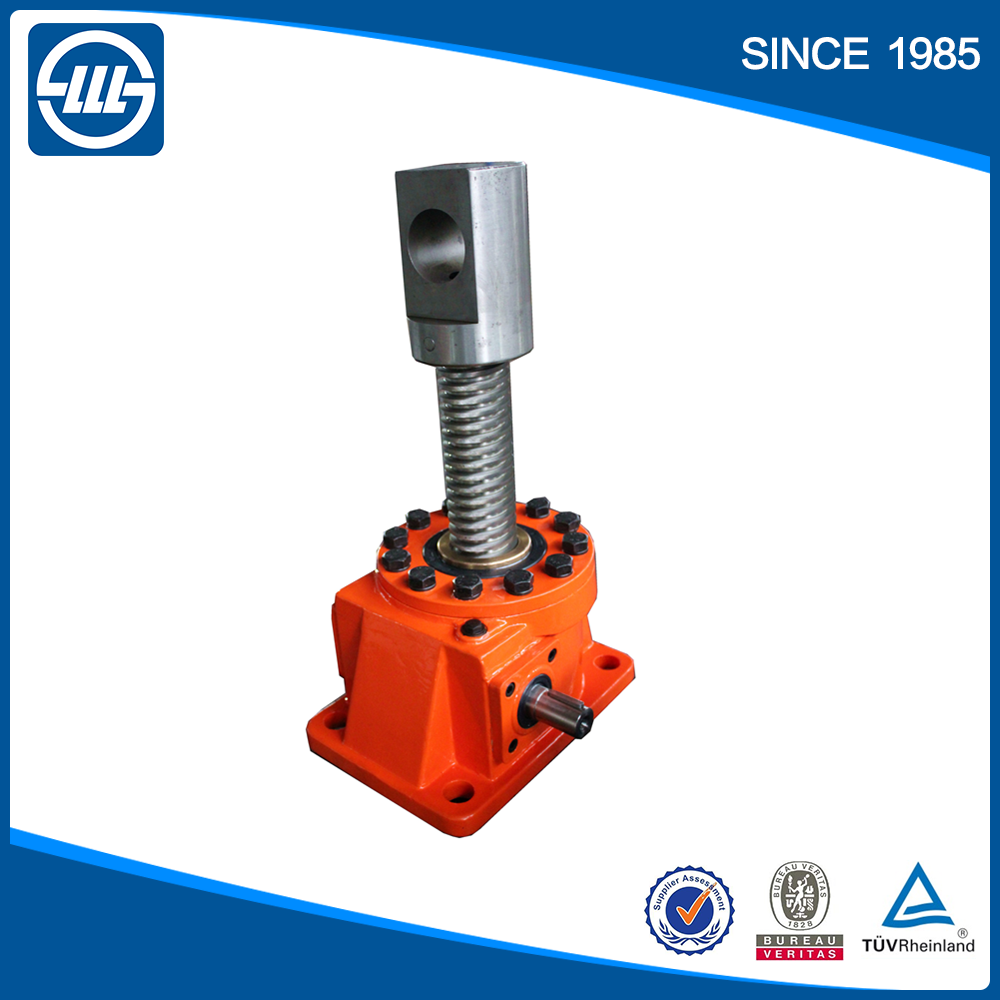
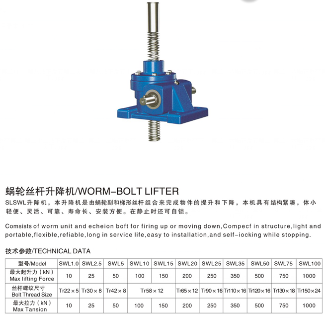
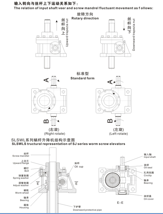

Certifications
Trade Shows
Packaging & Delivery
Packing Particulars : Standard carton/Pallet/Common wood situation
Shipping Details : 15-30 functioning days on payment

Business Information
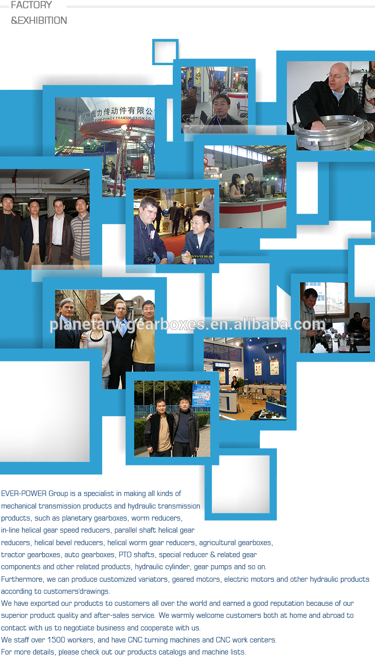
other sequence merchandise
| Precision Planetary gearbox | Robot RV gearbox speed reducer |
| Personalized manufactured Non-normal Gearbox | UDL Series Variator |
| PYZ Collection Helical Tooth Shaft Mounted Reducer | 8000 Series Cycloidal Reducer |
| SLT Series Spiral Bevel Gearbox | SLSWL Series Worm Screw Jack |
| SLP Sequence Planetary Reducer | SLH/SLB Sequence Substantial Energy Reducer |
| NMRV Series Worm Reducer | BKM Sequence Helical-hypoid Reducer |
| SLRC Collection Helical Reducer | SLSMR Series Shaft Mounted Reducer |
| SLXG Collection Shaft Mounted Reducer | X/B Collection Cycloidal Reducer |
| SLR/SLF/SLK/SLS Series Helical Reducer |
Related Merchandise
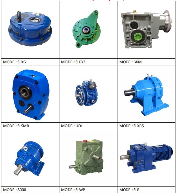
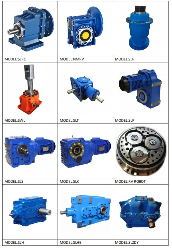
Get in touch with