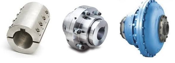
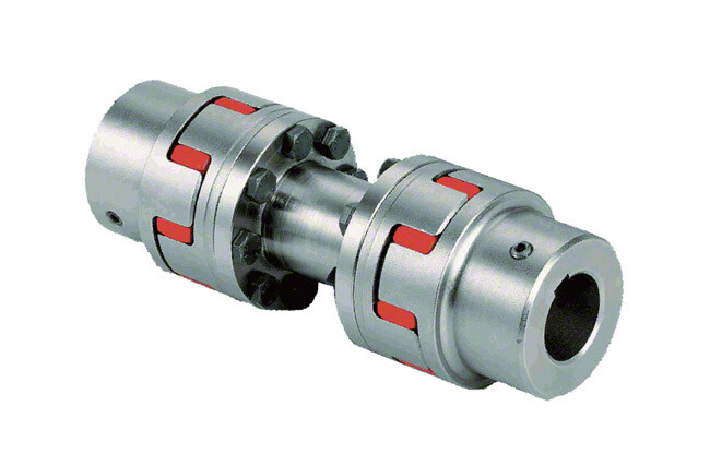
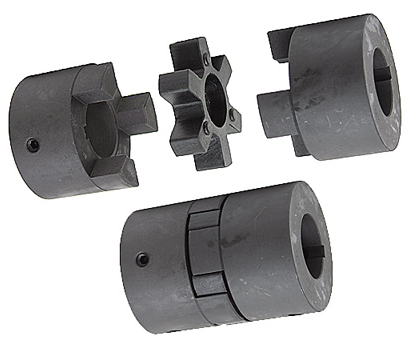
Product Description
GR-32×42 GR Motor Shaft Coupling Rigid Coupling
Description of GR-32×42 GR Motor Shaft Coupling Rigid Coupling
>The material is aluminum alloy, and the middle bellows is made of stainless steel with excellent corrosion resistance
>Laser welding is used between bellows and shaft sleeve, with zero rotation clearance, suitable for CHINAMFG and reverse rotation
>Bellows structure can effectively compensate radial, angular and axial deviation
>Designed for servo motor stepper motor
>Fastening method of setscrew
Catalogue of GR-32×42 GR Motor Shaft Coupling Rigid Coupling
|
model parameter |
common bore diameter d1,d2 |
ΦD |
L |
LI |
L2 |
L3 |
N |
F |
tightening screw torque |
|
GR-16×27 |
4,5,6,6.35,7,8 |
16 |
27 |
7.5 |
2 |
8 |
13.5 |
3 |
0.7 |
|
GR-20×32 |
5,6,6.35,7,8,9,9.525,10,11,12 |
20 |
32 |
7.2 |
2.8 |
12 |
18 |
3.5 |
0.7 |
|
GR-22.5×34 |
5,6,6.35,7,8,9,9.525,10,11,12 |
22.5 |
34 |
8.05 |
2.8 |
12.3 |
20.2 |
4.5 |
1.7 |
|
GR-25×37 |
6,6.35,7,8,9,9.525,10,11,12 |
25 |
37 |
9.5 |
3 |
12 |
20.2 |
4.5 |
1.7 |
|
GR-32×42 |
8,9,10,11,12,12.7,14,15 |
32 |
42 |
8 |
4 |
18 |
27.2 |
5.5 |
4 |
|
GR-40×51 |
8,9,9.525,10,11,12,12.7,14,15,16,17,18,19,20 |
40 |
51 |
9.5 |
6 |
20 |
34.5 |
5.5 |
4 |
|
GR-55×57 |
10,11,12,12.7,14,15,16,17,18,19,20,22,24,25 |
55 |
57 |
9 |
6 |
27 |
51.9 |
6.25 |
7 |
|
GR-65×81 |
10,11,12,12.7,14,15,16,17,18,19,20,22,24,25,28,30,32,35,38 |
65 |
81 |
19.5 |
7 |
28 |
60.5 |
8.9 |
7 |
|
model parameter |
Rated torque(N.m) |
allowable eccentricity (mm) |
allowable deflection angle (°) |
allowable axial deviation (mm) |
maximum speed (rpm) |
static torsional stiffness (N.M/rad) |
weight (g) |
|
GR-16×27 |
0.8 |
0.1 |
2 |
-0.8 |
20000 |
150 |
8 |
|
GR-20×32 |
1.5 |
0.1 |
2 |
-1.2 |
18000 |
220 |
13 |
|
GR-22.5×34 |
1.8 |
0.15 |
2 |
-1.2 |
16000 |
300 |
22 |
|
GR-25×37 |
2 |
0.15 |
2 |
-1.2 |
15000 |
330 |
30 |
|
GR-32×42 |
2.5 |
0.2 |
2 |
-1.7 |
11000 |
490 |
53 |
|
GR-40×51 |
6.4 |
0.3 |
2 |
-1.7 |
10000 |
530 |
85 |
|
GR-55×57 |
12 |
0.3 |
2 |
-1.7 |
9000 |
860 |
170 |
|
GR-65×81 |
18 |
0.2 |
2 |
-1.8 |
4500 |
900 |
280 |
/* January 22, 2571 19:08:37 */!function(){function s(e,r){var a,o={};try{e&&e.split(“,”).forEach(function(e,t){e&&(a=e.match(/(.*?):(.*)$/))&&1

Can Shaft Couplings Compensate for Angular, Parallel, and Axial Misalignments?
Yes, shaft couplings are designed to compensate for different types of misalignments between rotating shafts in mechanical power transmission systems. They can handle the following types of misalignments:
- Angular Misalignment: This occurs when the shafts are not parallel and have an angle between them. Flexible couplings, such as elastomeric, beam, or Oldham couplings, can accommodate angular misalignments by allowing slight angular movement between the shafts while transmitting torque.
- Parallel Misalignment: This happens when the shafts are not collinear, resulting in axial displacement. Flexible couplings with lateral flexibility, like elastomeric or bellows couplings, can handle parallel misalignment by allowing limited lateral movement between the shafts.
- Radial Misalignment: Radial misalignment occurs when the shafts have lateral displacement but remain parallel. Flexible couplings, such as jaw or grid couplings, can absorb radial misalignment by permitting some lateral deflection while transmitting torque.
It is essential to note that while shaft couplings can compensate for misalignments to some extent, they do have their limits. The magnitude of misalignment they can handle depends on the type and design of the coupling. Exceeding the specified misalignment capabilities of a coupling can lead to premature wear, reduced efficiency, and possible coupling failure.
Therefore, when selecting a shaft coupling for an application, it is crucial to consider the expected misalignment and choose a coupling that can accommodate the anticipated misalignment range. Additionally, maintaining proper alignment through regular maintenance and periodic inspections is essential to ensure the coupling’s optimal performance and extend its service life.
“`
Do Shaft Couplings Require Regular Maintenance, and if so, What Does it Involve?
Yes, shaft couplings do require regular maintenance to ensure their optimal performance, extend their service life, and prevent unexpected failures. The maintenance frequency may vary based on factors such as the coupling type, application, operating conditions, and the manufacturer’s recommendations. Here’s what regular maintenance for shaft couplings typically involves:
1. Visual Inspection:
Regularly inspect the coupling for signs of wear, damage, or misalignment. Check for cracks, corrosion, and worn-out elastomeric elements (if applicable). Look for any abnormal movement or rubbing between the coupling components during operation.
2. Lubrication:
If the shaft coupling requires lubrication, follow the manufacturer’s guidelines for the appropriate lubricant type and frequency. Lubrication helps reduce friction, wear, and noise in the coupling.
3. Alignment Check:
Monitor shaft alignment periodically. Misalignment can lead to premature coupling failure and damage to connected equipment. Make adjustments as needed to keep the shafts properly aligned.
4. Torque Check:
For bolted couplings, periodically check the torque on the bolts to ensure they remain securely fastened. Loose bolts can lead to misalignment and reduce coupling performance.
5. Replace Worn Components:
If any coupling components show signs of wear or damage beyond acceptable limits, replace them promptly with genuine replacement parts from the manufacturer.
6. Environmental Considerations:
In harsh environments with exposure to chemicals, moisture, or extreme temperatures, take additional measures to protect the coupling, such as applying corrosion-resistant coatings or using special materials.
7. Monitoring Coupling Performance:
Implement a monitoring system to track coupling performance and detect any changes or abnormalities early on. This could include temperature monitoring, vibration analysis, or other condition monitoring techniques.
8. Professional Inspection:
Periodically have the coupling and connected machinery inspected by qualified professionals to identify any potential issues that may not be apparent during regular inspections.
By adhering to a regular maintenance schedule and taking proactive measures to address potential issues, you can ensure that your shaft couplings operate reliably and efficiently throughout their service life, minimizing downtime and improving overall system performance.
“`
Diagnosing and Fixing Common Issues with Shaft Couplings
Regular inspection and maintenance of shaft couplings are essential to detect and address common issues that may arise during operation. Here are steps to diagnose and fix some common coupling problems:
1. Abnormal Noise or Vibration:
If you notice unusual noise or excessive vibration during equipment operation, it may indicate misalignment, wear, or damage in the coupling. Check for any visible signs of damage, such as cracks or deformations, and inspect the coupling for proper alignment.
Diagnosis:
Use a vibration analysis tool to measure the vibration levels and identify the frequency of the abnormal vibrations. This can help pinpoint the source of the problem.
Fix:
If misalignment is the cause, adjust the coupling to achieve proper alignment between the shafts. Replace any damaged or worn coupling components, such as spiders or elastomeric inserts, as needed.
2. Excessive Heat:
Feeling excessive heat on the coupling during operation can indicate friction, improper lubrication, or overload conditions.
Diagnosis:
Inspect the coupling and surrounding components for signs of rubbing, lack of lubrication, or overloading.
Fix:
Ensure proper lubrication of the coupling, and check for any interference between the coupling and adjacent parts. Address any overloading issues by adjusting the equipment load or using a coupling with a higher torque capacity.
3. Shaft Movement:
If you observe axial or radial movement in the connected shafts, it may indicate wear or improper installation of the coupling.
Diagnosis:
Check the coupling’s set screws, keyways, or other fastening methods to ensure they are secure and not causing the shaft movement.
Fix:
If the coupling is worn or damaged, replace it with a new one. Ensure proper installation and use appropriate fastening methods to secure the coupling to the shafts.
4. Sheared Shear Pin:
In shear pin couplings, a sheared shear pin indicates overloading or shock loads that exceeded the coupling’s torque capacity.
Diagnosis:
Inspect the shear pin for damage or breakage.
Fix:
Replace the sheared shear pin with a new one of the correct specifications. Address any overloading issues or adjust the equipment to prevent future shearing.
5. Coupling Wear:
Regular wear is normal for couplings, but excessive wear may lead to decreased performance and increased misalignment.
Diagnosis:
Inspect the coupling components for signs of wear, such as worn elastomeric elements or damaged teeth.
Fix:
Replace the worn or damaged components with new ones of the appropriate specifications.
Remember, regular maintenance and periodic inspection are key to diagnosing issues early and preventing severe problems. Always follow the manufacturer’s recommendations for maintenance and replacement schedules to ensure the proper functioning and longevity of the shaft coupling.
“`

editor by CX 2024-05-09